

Table of Contents
Harmonics and A Guide on How To Choose the Correct Filter Reactor
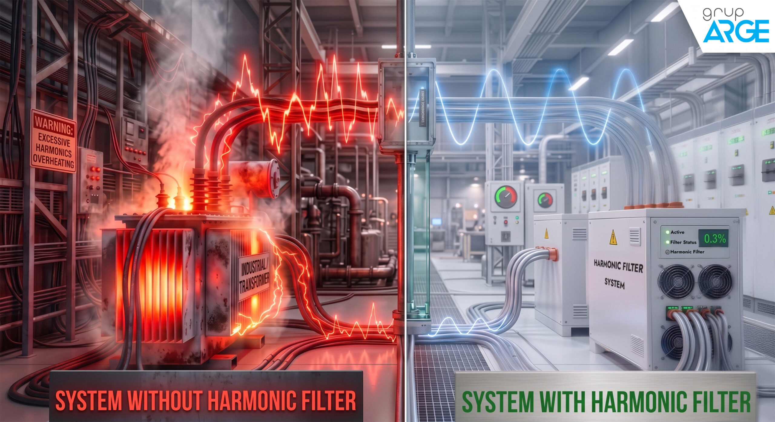
As the industrial plants got digitalized and automated, the power electronic based loads have increased rapidly. However, this modern transformation, ranging from motors to LED illumination, has also brought a serious power quality problem in power grids called “Harmonic Distortion”. As Grup Arge, it is our primary objective to protect hardware safety and system sustainability while minimizing the reactive power penalty risks.
Accordingly, we’ve put up a guide about harmonic filter reactors that directly determines the electrical stability of plants, and how to choose the correct components.
What is a Harmonic and Why Does It Occur?
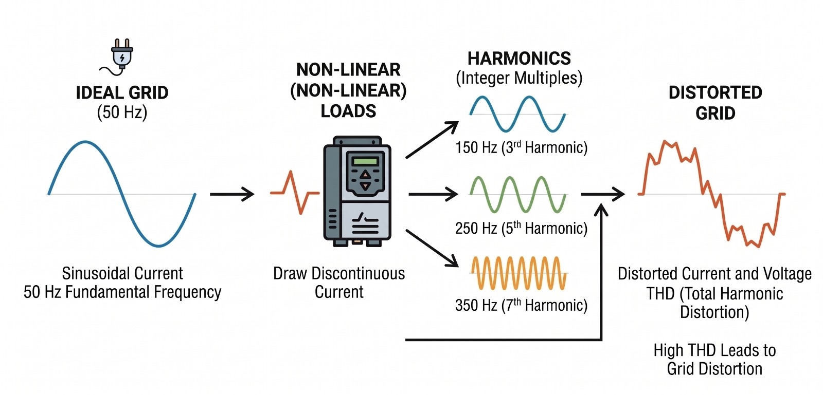
The current and voltage wave drawn from the grid is a perfect sinusoidal wave with a frequency of 50 Hz. However, non-linear loads draw the current as non-sinusoidal chopped waves. This chopped wave causes high frequency additional waves that are multiples of 50 Hz (100 Hz, 150 Hz, 250 Hz etc.), and these additional waves are called Harmonics.
Harmonics distort the current and voltage drawn from the grid by combining with the base wave, and this is called a Total Harmonic Distortion (THD) percentage in the industry. The distortion in the current is called THD-I, and in the voltage is called THD-V.
Primary Harmonic Sources in Plants
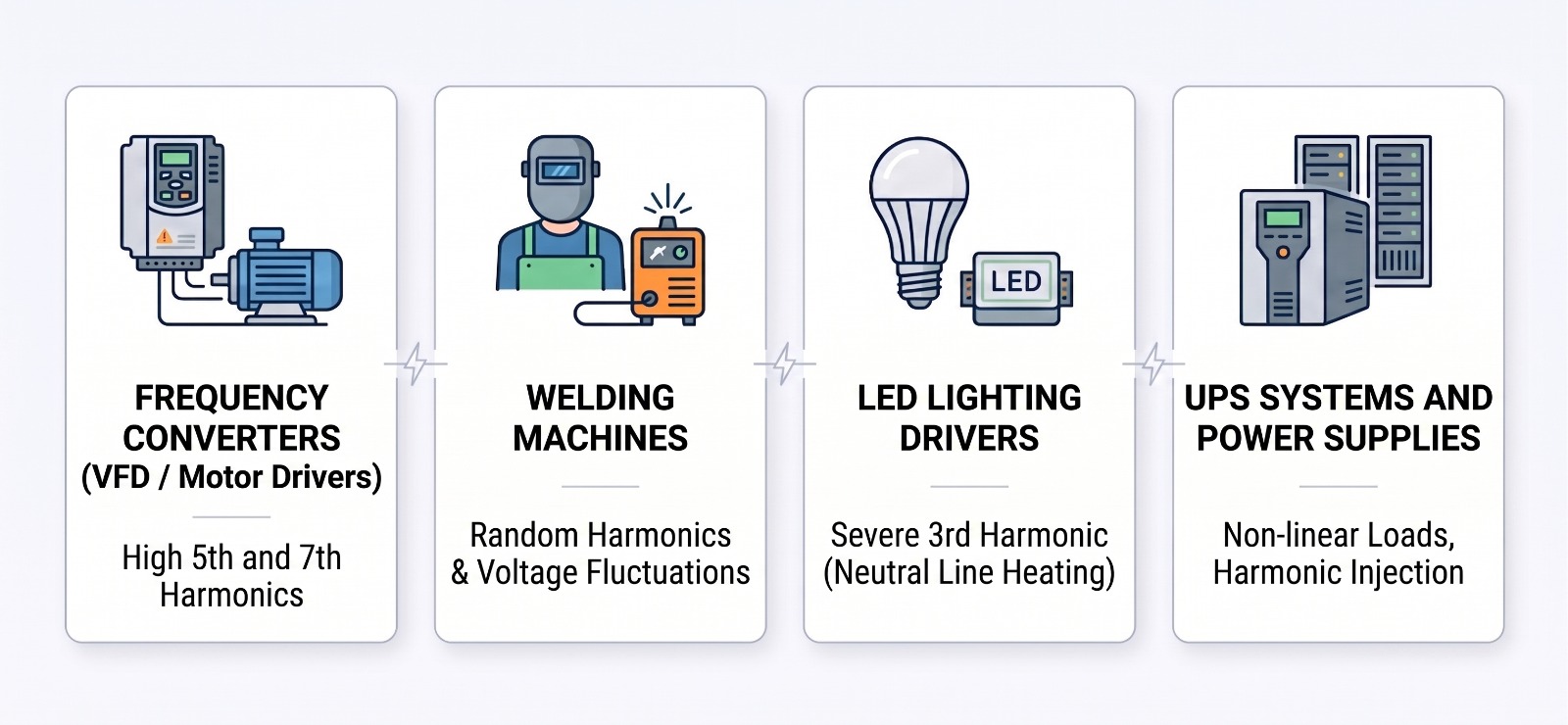
The primary equipment in an industrial facility that degrades power quality and generates significant harmonics is as follows:
- Frequency Converters: Holding a three phase power electronic, these systems especially create 5th (250 Hz) and 7th (350 Hz) harmonics intensely.
- Welding Machines: Arc and inverter welding machines cause irregular and high amplitude harmonics, while also causing flickers because of rapidly changing loads.
- LED Lighting Drivers: These monophase loads can cumulatively generate 3rd harmonics if there is a large number of them in a plant, especially if they are of low quality. 3rd harmonics and the multiples of it can cause the neutral line to overheat because they overlap instead of eliminating each other.
- UPS Systems and Power Plants: Because of their non-linear nature, UPS systems also inject harmonics into the grid.
What Are the Different Types of Harmonic Filters?
There are two main types of filters used in industrial plants to maintain power quality and prevent the destructive effects of harmonic distortion (THD): Active Harmonic Filters and Passive Harmonic Filters.
Although both serve the purpose of protecting the grid from the negative effects of harmonics, they differ in terms of their working principles, costs, and application methods.
Passive Harmonic Filters
Passive filters are traditional filter systems created by connecting static (passive) circuit components such as inductance (L), capacitance (C), and sometimes resistance (R) in series or parallel. These filters operate based on electrical impedance principles and are divided into two categories: Tuned Filters and Detuned Filters.
Tuned Passive Filters
Tuned filters are “harmonic filters” specially designed to directly eliminate a specific harmonic frequency in the grid.
Working Principles
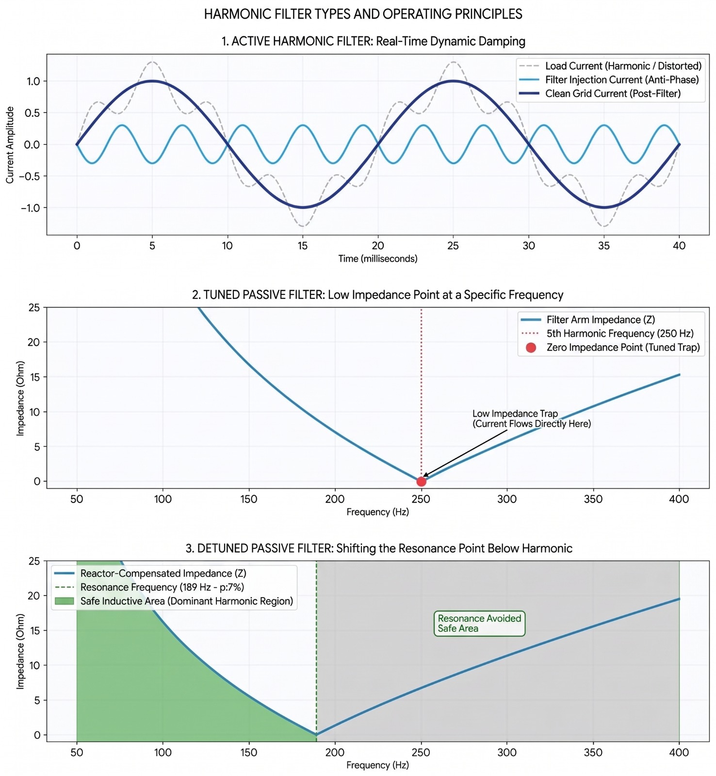
- The resonant frequency of the filter is tuned to the dominant harmonic frequency in the facility (for example, to 250 Hz for the 5th harmonic or 350 Hz for the 7th harmonic).
- The L-C circuit, connected in series, exhibits minimum impedance (zero in theory) at the tuned frequency.
- This creates a short-circuit path for the targeted harmonic current to flow through the filter instead of the grid. Harmonics are drawn to the filter and dampened before diffusing to the grid.
Detuned Passive Filters
- Detuned filters are designed to protect the compensation system from resonance risks instead of cleaning out the harmonics.
Working Principles
- The main purpose is to prevent capacitors from resonating with the grid inductance and causing a current overload.
- In these systems, the resonant frequency of the LC circuit, formed by the reactor (L) and the capacitor (C), is set below the smallest existing harmonic frequency in the grid.
- Because the tuning frequency is shifted away from the harmonic frequencies, the system is called “detuned”.
Active Harmonic Filters
These are power electronics-based, dynamically operating high-tech systems that simultaneously monitor the harmonic distortion that occurs in electrical systems, and neutralize these distortions with a reverse-phase current they generate.
Working Principles
- It samples the current and voltage in the system a great number of times and detects harmonic components.
- It generates a damping current in the exact opposite phase of the detected harmonic currents and injects it into the grid.
- Thus, the harmonic current generated by the load and the reverse current generated by the filter neutralize each other, leaving only a clean, sinusoidal current on the grid.
How to Determine the Resonance Frequency and “p” Factor (Tuning)
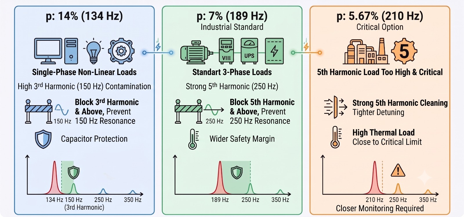
The tuning frequency of a passive filter circuit or a detuned reactor is determined by the Tuning Factor (p). The most common p values selected based on facility structures are:
- p: 14% (134 Hz): It is used when monophase non-linear loads (computers, LED lighting, building automation systems) are dense in the facility and 3rd harmonic (150 Hz) pollution is high. By lowering the resonance frequency to 134 Hz, it prevents the system from resonating at the 3rd harmonic (150 Hz) and higher harmonics. It also provides safety for capacitors in grids with high voltage harmonics.
- p: 7% (189 Hz): It is the most widely used value in industrial plants. It is chosen if standard three-phase loads such as motor drives (VFD), UPS systems, and rectifiers are the mainly used devices. By creating a resonance point (189 Hz) below the 5th harmonic (250 Hz) frequency, which is the strongest harmonic produced by these loads, it prevents the system from resonating at the 5th harmonic and higher harmonics, effectively blocking them.
- p: 5.67% (210 Hz): It can be used if the 5th harmonic (250 Hz) load across the plant is at an extremely high and critical level. It sets the resonance frequency to 210 Hz, bringing it closer to the 5th harmonic (250 Hz), causing the filter to draw the 5th harmonic currents at a higher rate compared to a 7% filter. This provides a cleaner system. However, the current and thermal load on the reactor intensifies because of this process. Additionally, since possible reductions in capacitor capacity because of aging can bring the resonance frequency closer to the critical 250 Hz limit, it is important to monitor and maintain the system periodically.
How to Determine Reactor Endurance?
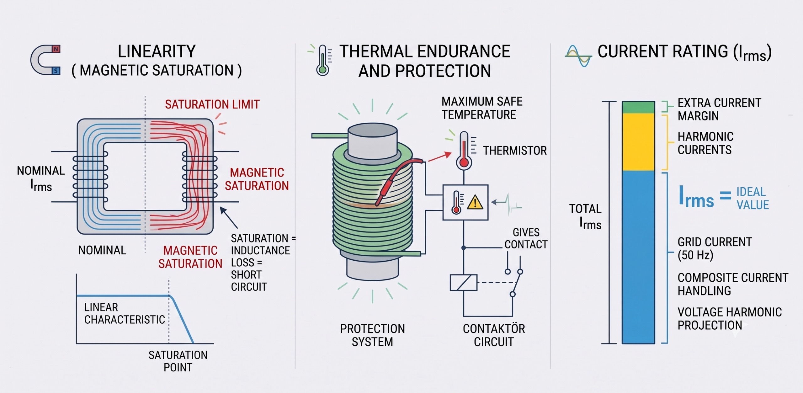
To ensure harmonic filter reactors have a longer lifespan under harsh industrial conditions, the following are taken as references:
- Linearity (Magnetic Saturation Limit): When the current passing through the reactors increases, the magnetic core must not enter saturation. This coefficient, indicating until when the linear characteristic is intact, is of utmost importance. When a saturated reactor loses its inductance, it acts like a straight cable (short circuit), leaving the system open to resonance danger.
- Thermal Endurance and Protection: Reactors inherently generate heat while operating. Therefore, standard designs include a thermistor embedded in the coils that provides a contact when the maximum safe temperature is exceeded. This thermal contact must be connected to the contactor circuit of the relevant step.
- Current Endurance: It is the capacity to carry the total effective current, which is the sum of grid current and upper harmonic currents. Additional current margins are calculated by predicting that the system will withstand a certain voltage harmonic in the designing phase.
The Importance of the Filter Reactor and Selecting the Right Capacitor
When setting up a compensation circuit with a harmonic filter, the reactor (L) and capacitor (C) are like two pans of a scale. A reactor connected in series raises the voltage above the grid voltage at the capacitor terminal.
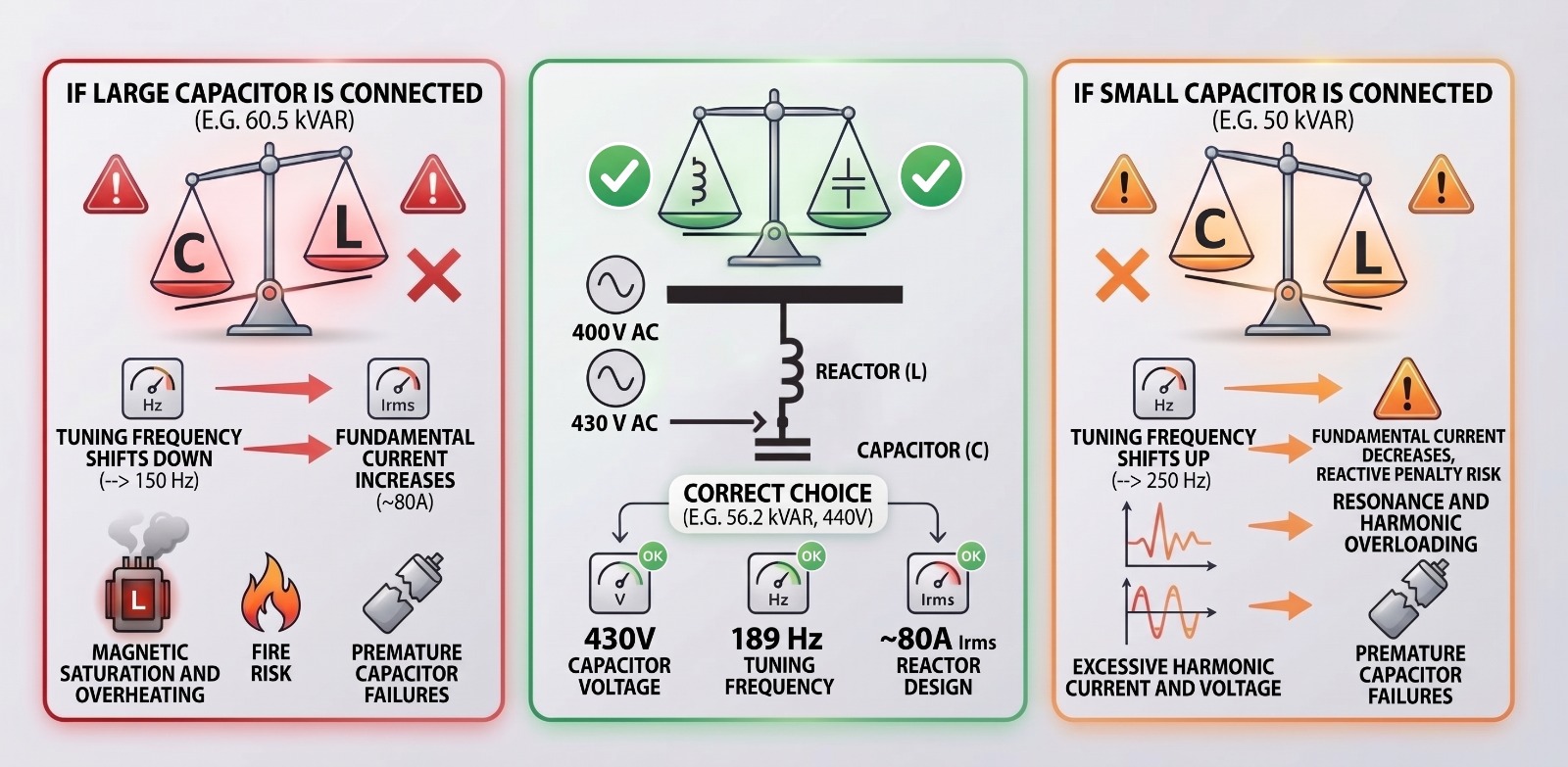
For example, when a filter with p = 7% is used at a 400V grid voltage, the voltage at the capacitor terminals continuously rises to around 430V. Because of this, it is important to choose a capacitor with a minimum voltage level of 440V in such systems. If the aim is to get 50 kVAr power nominally, a 440V capacitor should be selected as 56.2 kVAr and should draw approximately 72A of current at the fundamental frequency. When the standard harmonic current endurance margin (~30A) is added, the total Irms current design of the reactor is balanced around 80A.
So, What Happens If We Deviate From This Calculation and Connect a 60.5 kVAr Capacitor Instead of 56.2 kVAr?
- Tuning Frequency Goes Down: Because a higher capacitance (C) is included in the circuit, the tuning frequency goes down to around ~182 Hz from 189 Hz. This brings the filter dangerously close to the 3rd harmonic (150 Hz), and uncontrolled harmonic is drawn from the grid.
- Fundamental Current Increases: As the power increases, the nominal current at 50 Hz goes up to 78A – 80A from ~72A . The system reaches its limits before any harmonic load even arrives.
- Magnetic Saturation and Overheating: With the addition of harmonics, the total Irms current goes up to 85A-90A. This overload can drive the reactor core into magnetic saturation. The inductance value (mH) of a saturated reactor collapses rapidly, overheating coils, scorching insulation, and increasing the buzzing and noise excessively, creating a risk of fire in the panel.
- Premature Capacitor Failures: Excessive current and voltage stress quickly exhaust the life of cylindrical capacitors, causing internal overpressure fuses to blow or dry out, leading to capacity loss.
Conversely, If a 50 kVAr Capacitor is Connected Instead of 56.2 kVAr;
- Tuning Frequency Goes Up: Because a lower capacitance (C) is included in the circuit, the tuning frequency goes up, rising to around ~201 Hz from 189 Hz. This brings the filter dangerously close to the 5th harmonic (250 Hz), which is the most common and strongest in the grid, and uncontrolled harmonic current is drawn from the grid.
- Fundamental Current Drops and Compensation is Insufficient: Since capacitive power decreases, the nominal fundamental current at 50 Hz falls back to around 64A from ~72A. Although the fundamental current seems to have dropped, the reactive power compensation capacity of the system decreases significantly, which means the plant cannot reach the target power factor, and a risk of reactive power penalties arises.
- Resonance Instability and Overloading: The tuning frequency approaching the 5th harmonic lowers the filter’s impedance at this frequency. The 5th harmonic components, produced by devices like motor drives in the grid, practically rush to the filter branch. The decreasing fundamental current is replaced by uncontrollably rising harmonic currents; the total Irms value exceeds safety limits, leading to reactor overheating and resonance instability.
- Premature Capacitor Failures: The excessive harmonic current created by approaching the resonance, and the harmonic voltage rise because of it, can quickly consume the dielectric material and lifespan of cylindrical-type capacitors. Overheated capacitors cause blown or dried out internal overpressure fuses, becoming out of use.
Benefits of Choosing the Right Harmonic Filter
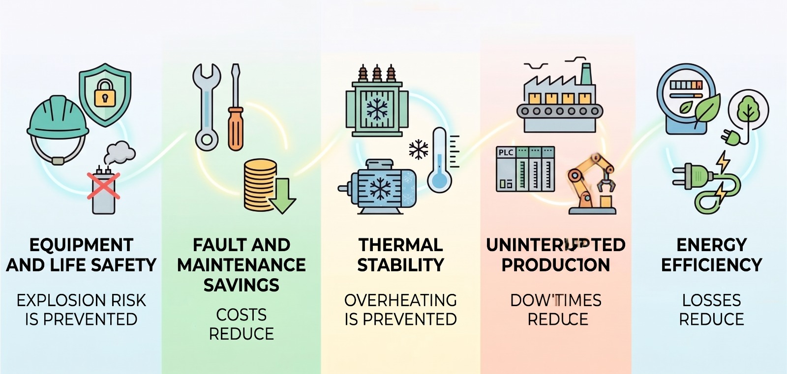
A harmonic filter system, designed according to the electrical structure of the plant, provides benefits to businesses such as:
- Equipment and Life Safety: It eliminates overheating, swelling, and explosion risks of compensation capacitors.
- Cost Reduction: It decreases fuse blowouts and prevents contactor stickiness and premature lifespan losses.
- Thermal Stability: It prevents transformers, motors, and cables in panels (especially neutral lines) from wearing out due to overheating.
- Uninterrupted Production: It prevents sensitive electronic devices (PLCs, automation cards, microcontroller systems) from experiencing harmonic-induced failures, thus reducing downtime costs.
- Energy Efficiency: It improves overall efficiency across the facility by preventing additional heat losses created by harmonic currents in cables and transformers.
Conclusion: The First Step in Power Quality is Always Accurate Measurement!
Choosing filter reactors and capacitors blindly, relying solely on catalog data or estimates can trigger resonance risks and cause greater electrical damage instead of protecting the business. Harmonic profiles, dominant harmonic orders, and load variabilities of each industrial facility are unique.
As Grup ARGE, we believe that the first and most critical step in managing power quality is precise power quality analysis and spectrum measurement. We analyze your facility with our self-designed, high-tech reactive power control relays, energy analyzers, and expert engineering staff. We then design compensation solutions with harmonic filters that are up to international standards while having the most efficient and accurate combination possible.
If you experience frequent capacitor failures, unexplained switching problems, or overheating inside panels, you can contact our expert team to request a power quality analysis. It is always good to keep in mind that sustainable production and operational safety begins with proper power quality management.