

Table of Contents
Hidden Dangers in Electrical and Power Factor Correction Panels: Common Mistakes, Risks, and Solutions
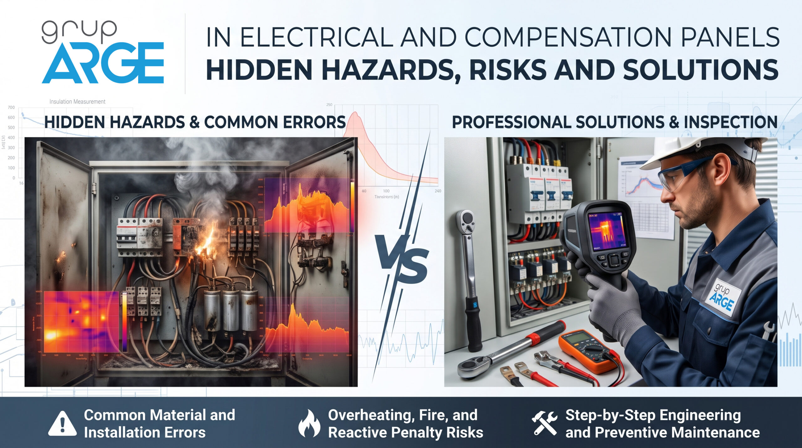
Electrical panels, and particularly power factor correction panels, serve as the critical hubs ensuring the uninterrupted, safe, and economical operation of industrial facilities and commercial buildings. However, even the slightest engineering error during panel design, component selection, or installation can lead to severe and costly consequences over time—ranging from overheating and abnormal noise to system inadequacy, reactive power penalties, and even panel fires.
In this article, we will detail the systemic and physical errors frequently encountered in electrical panels, analyze component-based risks, and present a step-by-step solution methodology to safeguard your facility.
Component Selection Errors and Their Impacts
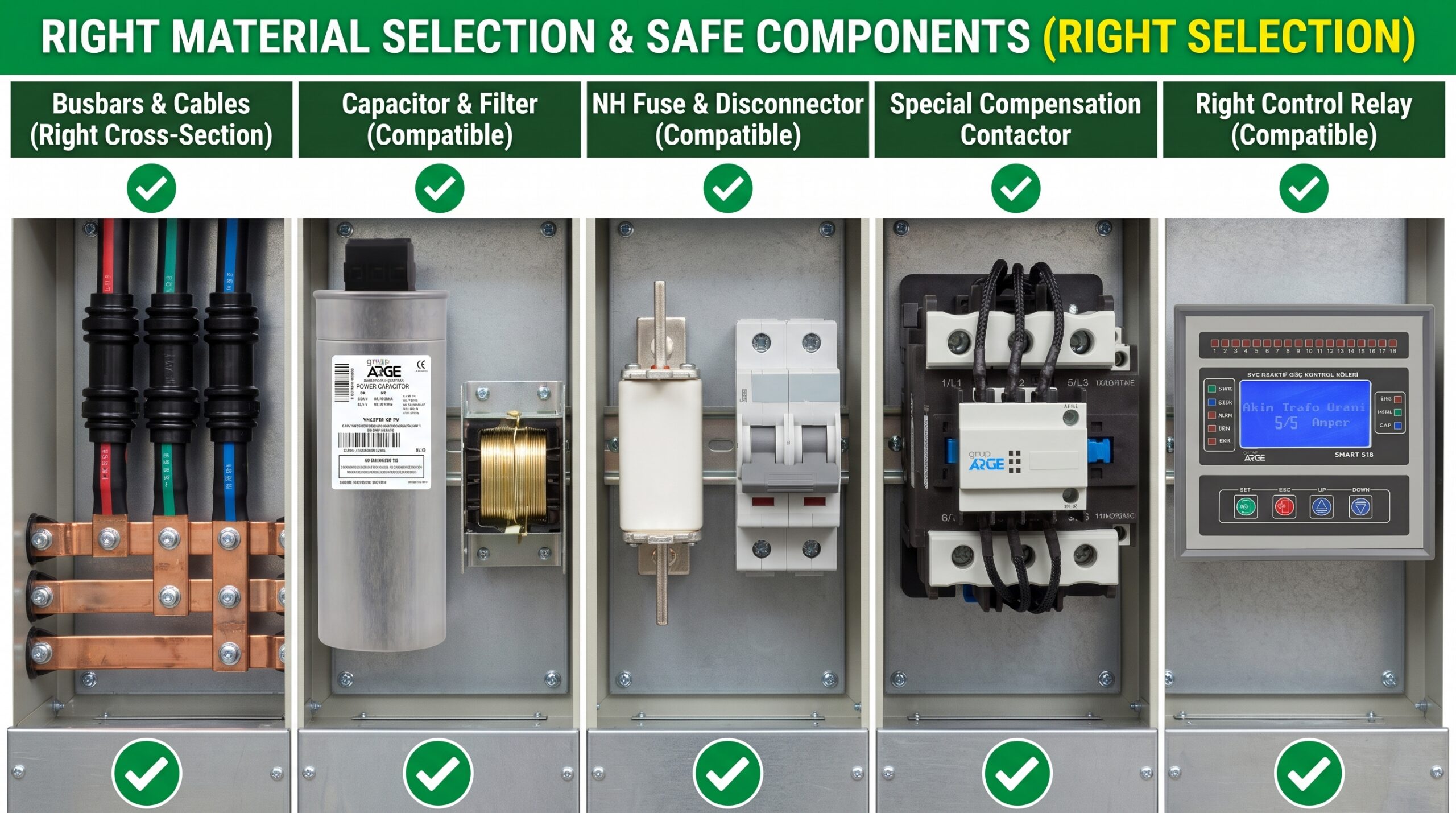
Improper material selection turns panels into potential failure points even before they are commissioned. The most critical selection errors in foundational components include:
Busbars and Cables (Incorrect Cross-Section Selection):
- Failing to consider ampacity, ambient temperature, and grouping factors results in cables continuously operating at their thermal limits. Undersized cables and busbars exhibiting high resistance will overheat, inviting insulation melting and short circuits.
Capacitor and Detuned Filter Incompatibility:
- In facilities with non-linear loads (VFDs, UPSs, induction furnaces), failing to use passive harmonic (detuned) reactors or applying incorrect resonance frequencies (e.g., p=7%, 14%) causes the system to enter resonance. This subjects capacitors to excessive voltage and current, leading to swelling, explosion, or rapid depletion of their lifespan.
NH Fuses and Switch Disconnectors:
- When the rated current and breaking capacity of the selected NH fuses do not align with the discharge currents and short-circuit characteristics of the connected load, the fuses will either blow without cause or melt during a short circuit, severely damaging the switch disconnector housing and the panel itself.
Contactors:
- Using standard power contactors in capacitor banks causes the contacts to weld together due to high inrush peak currents during switching. Capacitors that fail to disconnect lead to capacitive reactive penalties, capacitor explosions, and fire hazards.
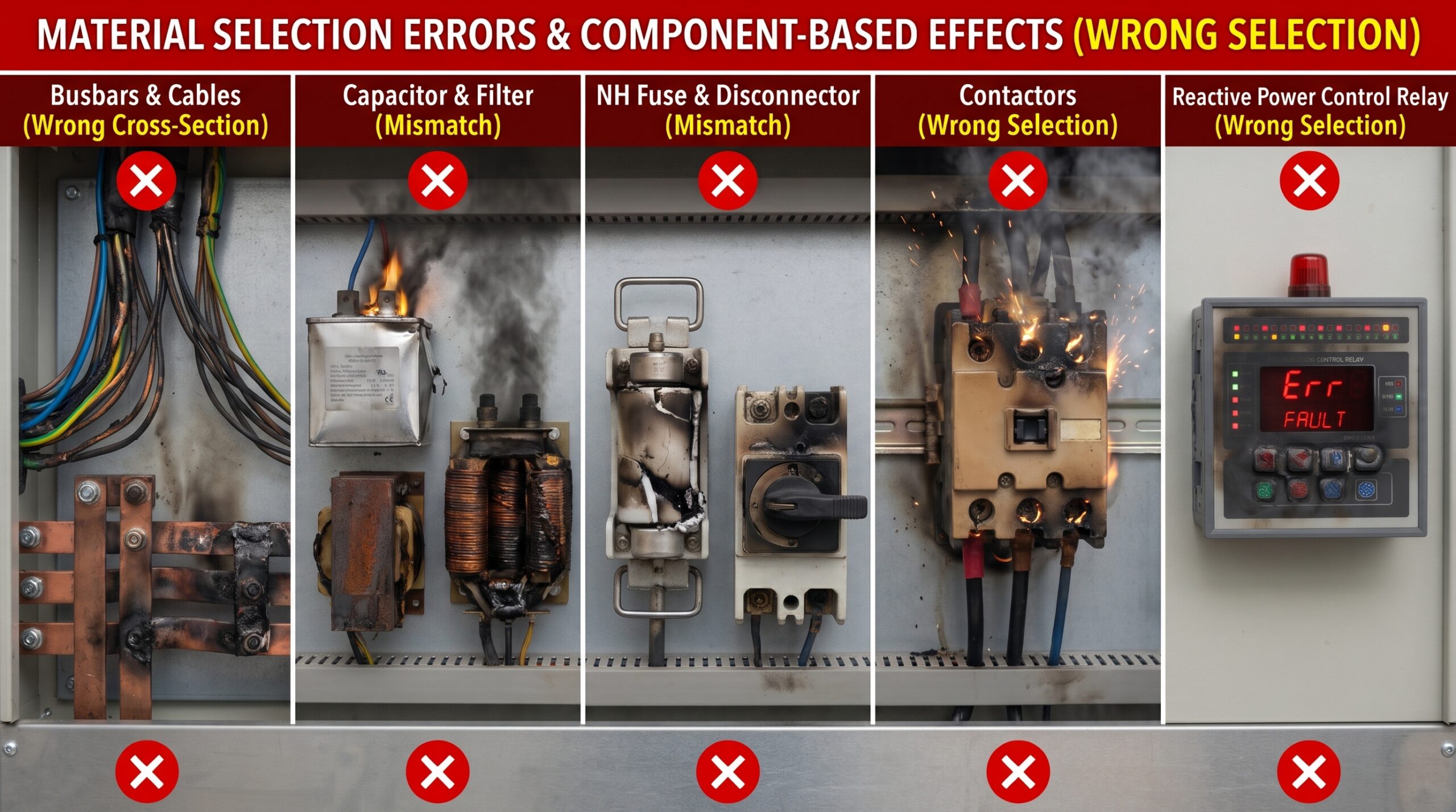
- To mitigate these risks, AC-6b duty Special Capacitor Switching Contactors must be preferred. Equipped with a pre-charge resistor block, these contactors damp damaging inrush currents within milliseconds, while their special silver-alloy main contacts ensure long-life and safe operation.
Power Factor Controllers:
- Selecting a relay that lacks accurate measurement precision, high sampling rates, and dynamic step management prevents the system from responding to rapidly changing reactive power demands, ultimately driving the facility into reactive power penalties.
Installation and Workmanship Errors
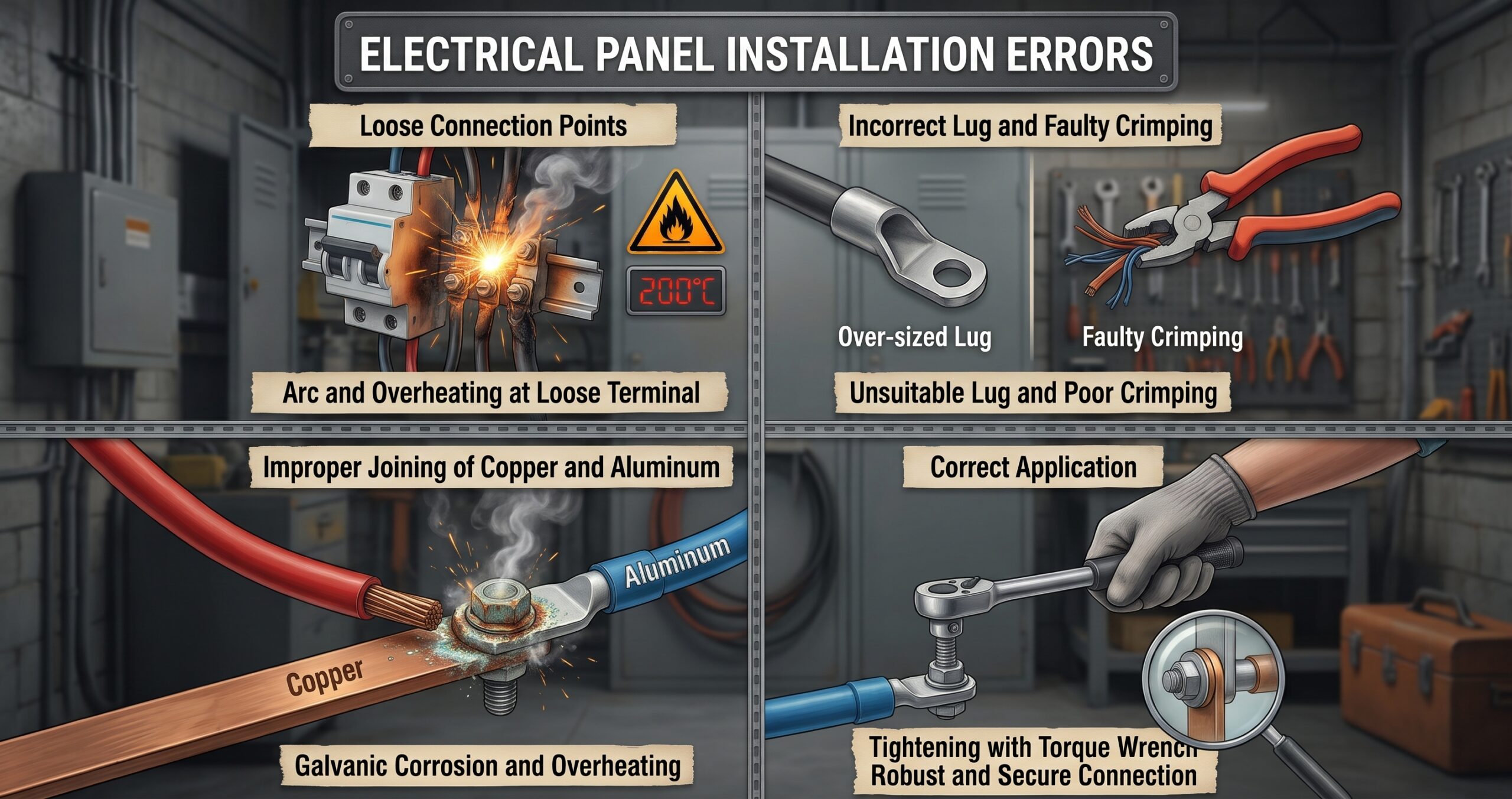
Even with the highest quality materials, faulty workmanship remains the leading cause of panel fires and malfunctions.
Loose Connection Points:
- Under-tightening or over-tightening bolts, terminals, and switch connections without a calibrated torque wrench leads to gradual loosening. Loose connections cause arcing, increased contact resistance, and localized hotspots that can easily exceed 200°C.
Incorrect Cable Lugs and Improper Crimping:
- Using improperly sized cable lugs and crimping them with inadequate hand tools rather than hydraulic/mechanical crimpers reduces the contact surface area between the conductor and the lug. This reduced area creates high electrical resistance, translating into continuous heat and power loss.
Improper Joining of Copper and Aluminum (Galvanic Corrosion):
- When a copper busbar or cable is in direct contact with an aluminum lug or busbar, moisture triggers galvanic corrosion (the battery effect). Over time, the aluminum surface oxidizes, loses its conductivity, and causes the joint to overheat, posing a severe fire risk. Bimetallic (Al/Cu) lugs or bimetallic washers must always be used for these connections.
Internal Thermal Design and Physical Layout Errors
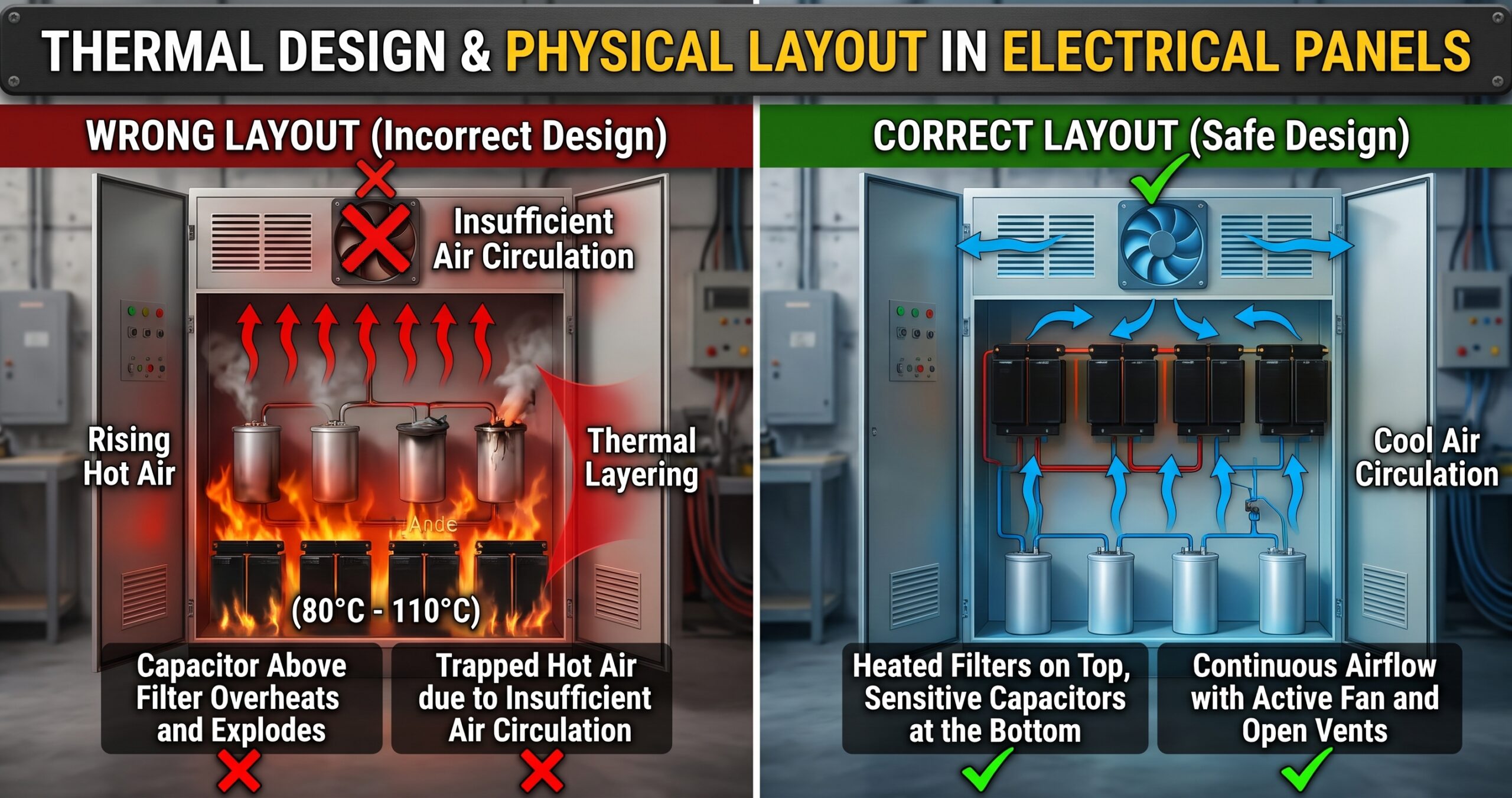
Ignoring the principle of convection (rising hot air) during panel layout directly shortens equipment lifespan.
Incorrect Component Layout:
- The most critical mistake in power factor correction panels is placing capacitors directly above passive harmonic filters (reactors). By design, harmonic filters generate significant heat (80°C – 110°C) during operation. Capacitors placed above them are exposed to this rising hot air. Consequently, the dielectric material and electrolyte inside the capacitor dry out, leading to rapid capacity loss and potential explosion.
Inadequate Air Circulation and Thermal Management:
- Selecting fan and filter systems without calculating the panel’s total heat load traps hot air inside. Blocking inlet and exhaust louvers causes thermal stratification and widespread component stress.
Operational and Power Quality – Related Degradation
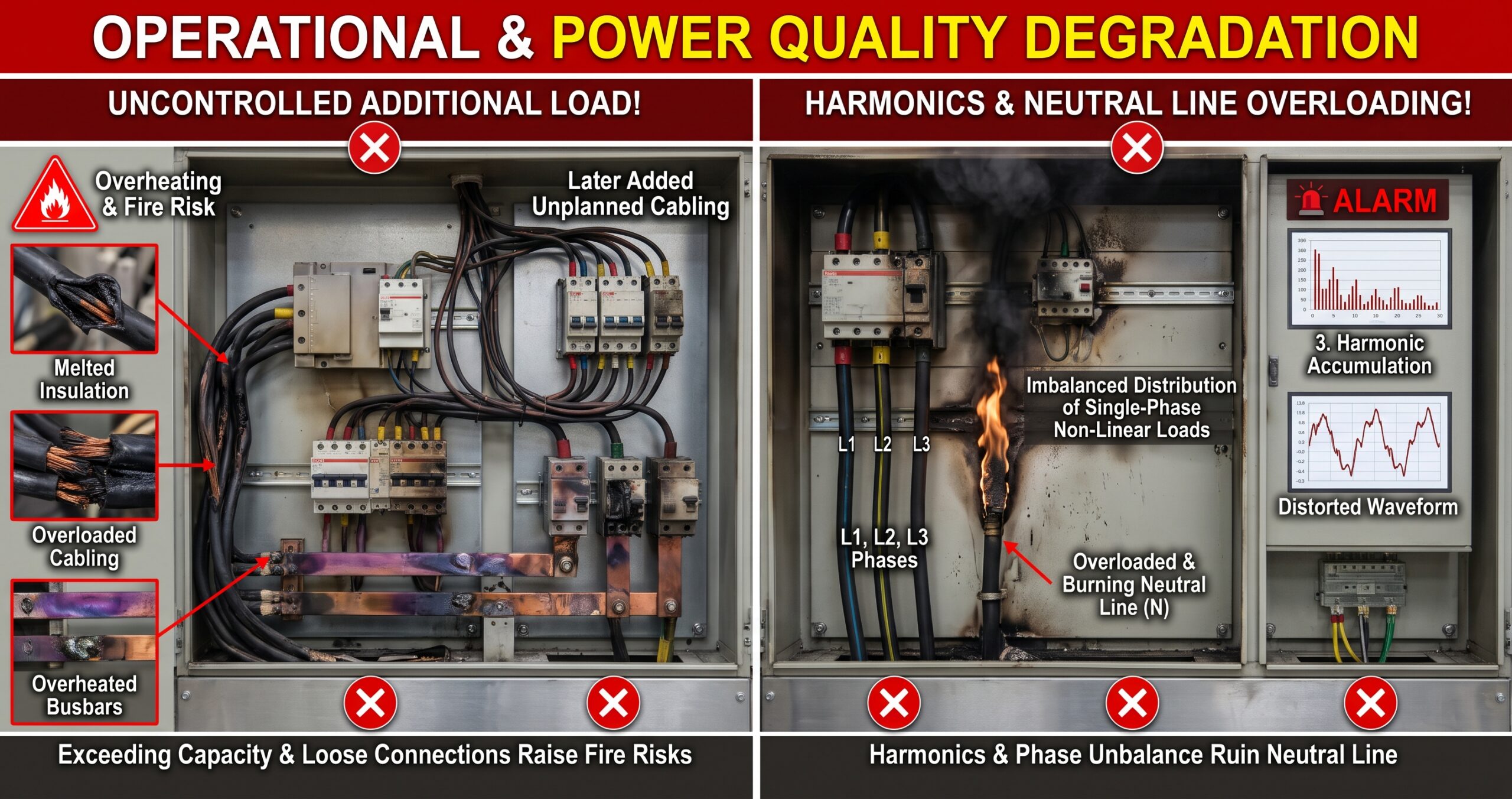
Uncontrolled Additional Loads Post-Project:
- As a facility expands, additional loads are often connected to existing panels without prior engineering assessment. This pushes busbars and feeder cables beyond their design limits, forcing them to operate under continuous overload and degrading insulation quality.
Neutral Wire Overloading Due to Harmonics and Phase Imbalance:
- Failing to distribute single-phase non-linear loads equally across phases leads to phase imbalance. Furthermore, 3rd and odd-multiple (triplen) harmonics accumulate on the neutral conductor of a 3-phase system rather than canceling each other out. Consequently, the neutral current can exceed the phase currents, bringing the neutral cable or busbar to the point of combustion.
Panel Warning Signals: Noise, Heat, and Performance Loss
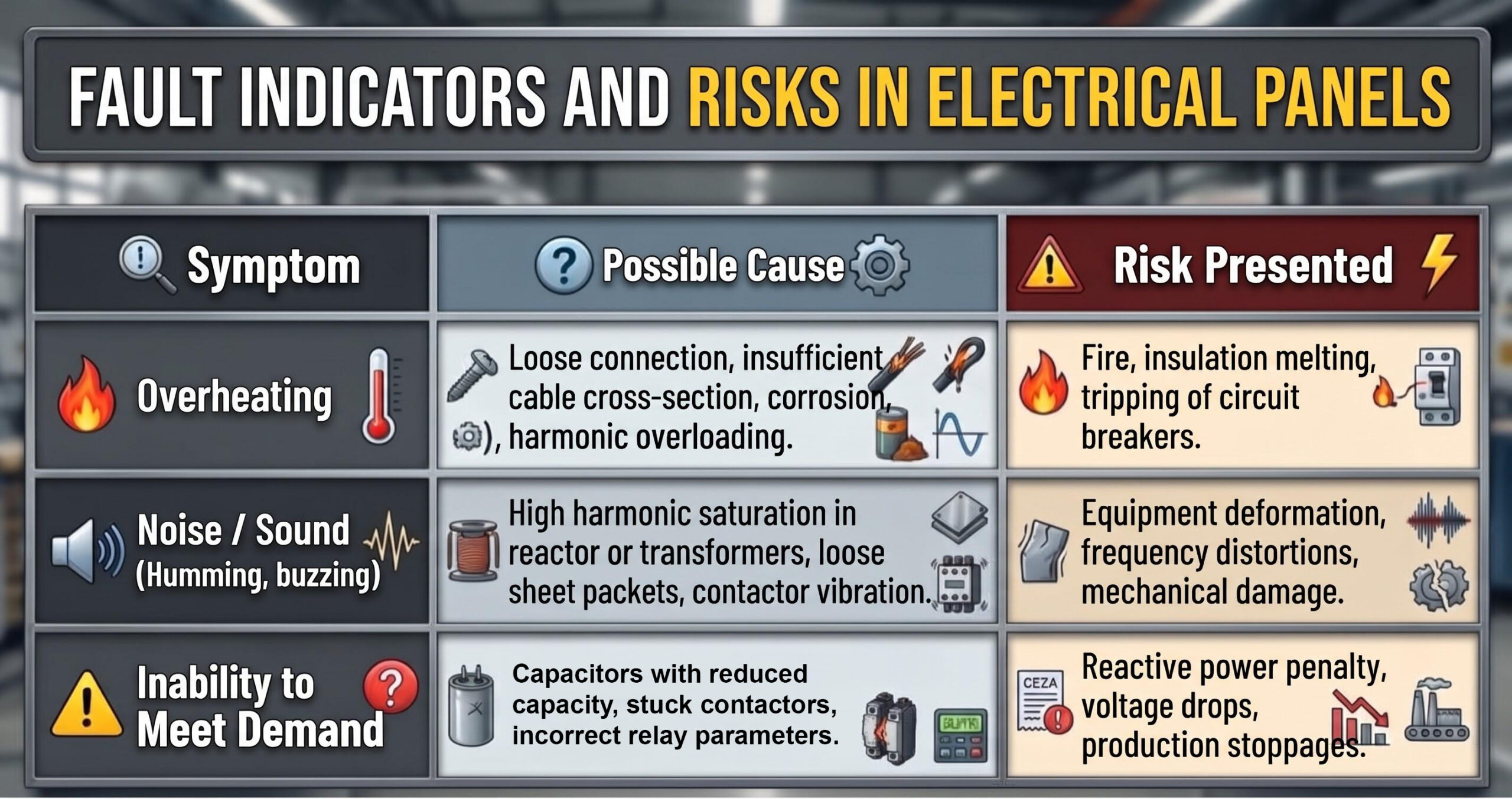
When an issue begins in a panel, the system exhibits three primary physical symptoms:
Step-by-Step Solution Methodology
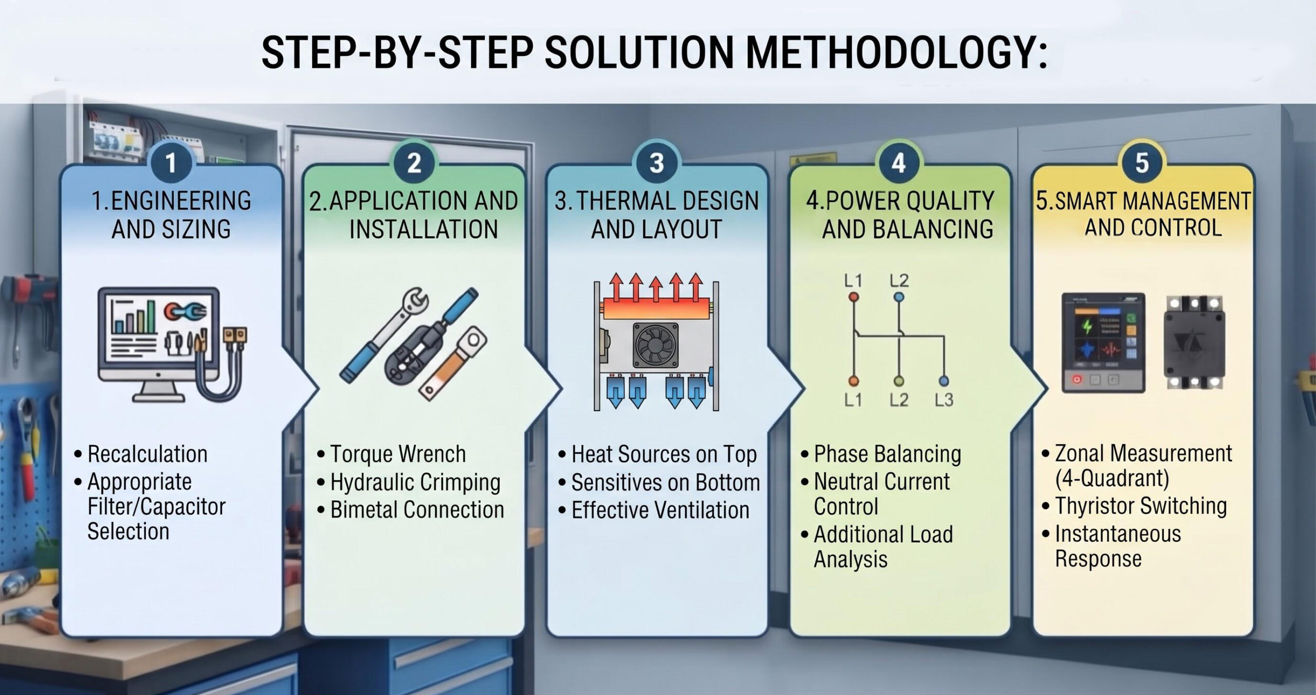
To eliminate all these risks in electrical and power factor correction panels, the following solution steps must be implemented:
Engineering and Sizing Revision:
- Re-calculate cable, busbar, and breaker cross-sections by analyzing the facility’s instantaneous load profile and harmonic spectrum.
- In systems with high harmonic distortion, always use passive harmonic (detuned) filters with the correct resonance frequency alongside heavily rated (high voltage endurance) capacitors fully compatible with these filters.
Enhancing Installation and Workmanship Standards:
- Tighten all connection points to the manufacturer’s specified torque values using a calibrated torque wrench.
- Select cable lugs strictly appropriate for the conductor cross-section and utilize hydraulic crimping tools.
- To prevent corrosion in copper-to-aluminum joints, the use of Bimetallic (Al/Cu) lugs or bimetallic washers is strictly required.
Thermal Design and Physical Layout Adjustments:
- Place heat-dissipating components (harmonic filters, shunt reactors) at the top of the panel or in independent, easily ventilated compartments.
- Position capacitors below reactors and heat sources, or in a separate thermally isolated section entirely.
- Calculate the required forced ventilation (fan/filter) capacity based on the total wattage loss to ensure proper internal airflow.
Power Quality and Balancing Interventions:
- Eliminate phase imbalances by evenly distributing single-phase loads across all three phases.
- To prevent triplen harmonics from overloading the neutral line, double the neutral cross-section relative to the phase conductors if necessary, or implement active neutral filtering solutions.
- Never draw new lines for post-commissioning loads without thoroughly analyzing the capacity of the existing busbars and conductors.
Smart Management and Intelligent Reactive Power Control:
- In power factor correction panels, power factor controllers that can respond to fast and precise steps are of vital importance. Especially in facilities with self-generation, such as rooftop PV or cogeneration systems, power flow continuously fluctuates; therefore, power factor controllers capable of 4-quadrant bidirectional (generation/consumption) measurement and power factor correction are essential.
- For rapidly changing loads, thyristor-based switching modules (solid-state switches) must be used instead of standard contactors.
Conclusion and Recommendations
Electrical and power factor correction panels should never be treated as “install and forget” systems. Proper material selection and high-quality installation form the baseline of safety; however, for long-term sustainability, periodic inspections and predictive maintenance are absolutely vital.
To prevent costly breakdowns and fire hazards in your facility:
- Inspect all panel connections, cable entries, and switch contacts with a thermal camera at least every 6 months.
- Periodically measure the current draw and capacitance values of your capacitors to identify and replace end-of-life steps before they fail.
- Clean dust and moisture from the panels regularly to verify the proper operation of ventilation fans and filters.
- Continuously monitor and record harmonic levels using professional power quality analyzers.
Remember; accurate engineering touches and regular, disciplined maintenance applied to your power factor correction and energy panels will not only drastically improve your facility’s power quality but also completely eliminate production losses and reactive power penalties.